A course about building a computer from scratch, right from the most basic logic gates to a fully functioning computer.
And we only need the NAND gate to build everything else as it is a universal gate (other logic gates can be built using the NAND gate itself). The truth table for NAND gate looks like this:
| A | B | Out |
|---|---|---|
| 0 | 0 | 1 |
| 0 | 1 | 1 |
| 1 | 0 | 1 |
| 1 | 1 | 0 |
And the NAND gate is represented as:
Basic Logic Gates
NOT Gate
To start with, let's build a NOT gate first which negates the input. It has probably the simplest design considering there is a single input and output and can be built using a single NAND gate.
| In | Out |
|---|---|
| 0 | 1 |
| 1 | 0 |
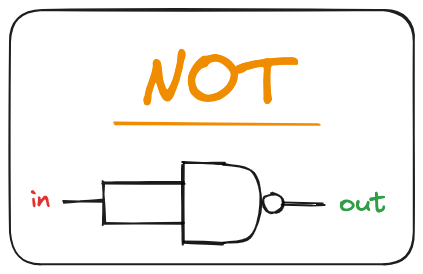
The NOT gate used further is represented as:
AND Gate
Next is the AND gate which returns 1 when both its inputs are 1, and 0 otherwise. It has the following truth table and can be built using 2 NAND gates.
| A | B | Out |
|---|---|---|
| 0 | 0 | 0 |
| 0 | 1 | 0 |
| 1 | 0 | 0 |
| 1 | 1 | 1 |
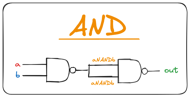
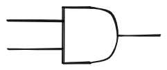
The AND gate used further is represented as:
OR Gate
The OR gate returns 1 when at least one of its inputs is 1, and 0 otherwise. It has the following truth table and can be built using 3 NAND gates.
| A | B | Out |
|---|---|---|
| 0 | 0 | 0 |
| 0 | 1 | 1 |
| 1 | 0 | 1 |
| 1 | 1 | 1 |
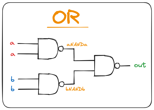
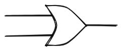
The OR gate used further is represented as:
XOR Gate
Another elementary gate is the XOR gate which returns 1 when its two inputs have opposing values, and 0 otherwise. It has the following truth table and can be built using 2 NOT, 2 AND and 1 OR gate.
| A | B | Out |
|---|---|---|
| 0 | 0 | 0 |
| 0 | 1 | 1 |
| 1 | 0 | 1 |
| 1 | 1 | 0 |
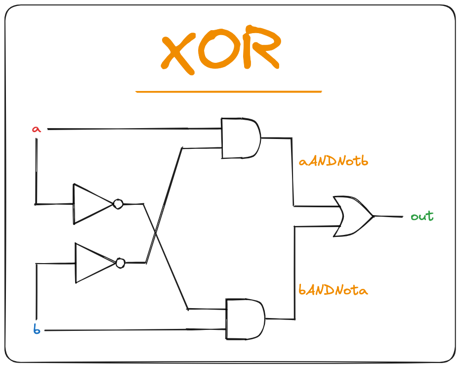
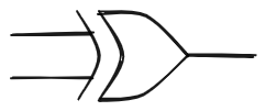
The XOR gate used further is represented as:
MUX
Now we can build a multiplexor (MUX). It is a three-input gate that uses one of the inputs, called selection bit to select and output one of the other two inputs, called data bits. The truth table looks like this:
| A | B | sel | Out |
|---|---|---|---|
| 0 | 0 | 0 | 0 |
| 0 | 0 | 1 | 0 |
| 0 | 1 | 0 | 0 |
| 0 | 1 | 1 | 1 |
| 1 | 0 | 0 | 1 |
| 1 | 0 | 1 | 0 |
| 1 | 1 | 0 | 1 |
| 1 | 1 | 1 | 1 |
It can built using 1 NOT, 2 AND and 1 OR gate.
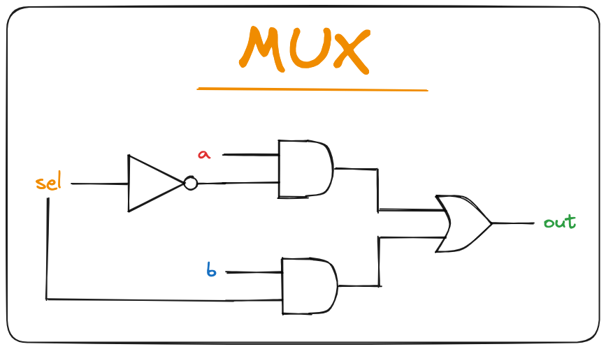
The MUX gate diagram used further is represented as:
DMUX
After the MUX, we need a demultiplexor (DMUX). It performs the opposite function of a multiplexor: It takes a single input and channels it to one of two possible outputs according to a selector bit that specifies which output to chose. The truth table looks like this:
| in | sel | A | B |
|---|---|---|---|
| 0 | 0 | 0 | 0 |
| 0 | 1 | 0 | 0 |
| 1 | 0 | 1 | 0 |
| 1 | 1 | 0 | 1 |
It can be built using 1 NOT and 2 AND gates.
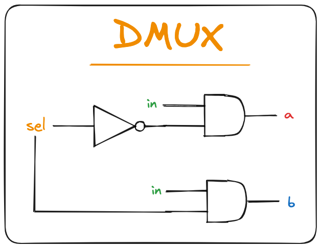
The DMUX gate diagram used further is represented as:
Multi-Bit versions of logic gates
Computer hardware is typically designed to operate on multi-bit arrays called buses. For purposes of this demonstration, we are going to be building the 16-bit versions of the logic gates. These gates can then take 16-bit input and produce a 16-bit output at once. The input can be accessed bit by bit (0 to 15) like an array and then routed to each single gate producing a single bit of output which can then be taken together to form the final 16-bit output.
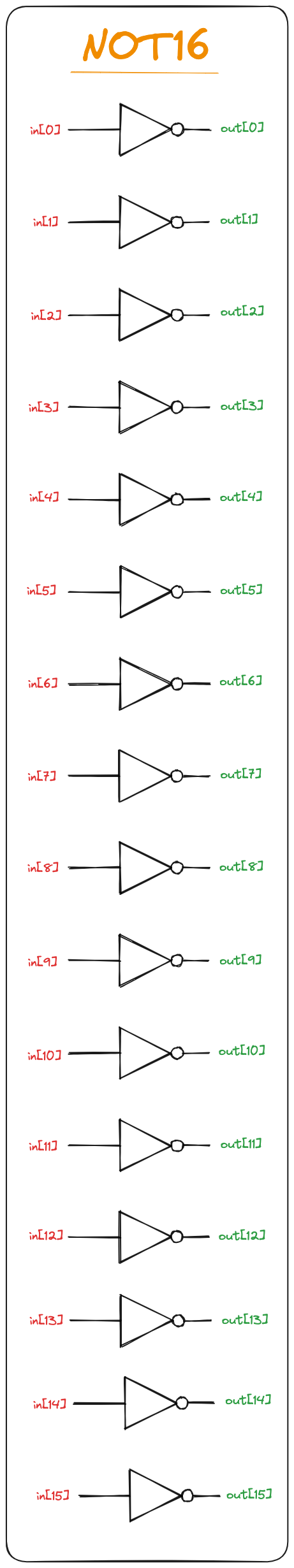
NOT16
An n-bit Not gate applies the Boolean operation Not to every one of the bits in its n-bit input bus. This is how a 16-bit NOT gate can be implemented which takes a 16-bit input and produces a 16-bit output.
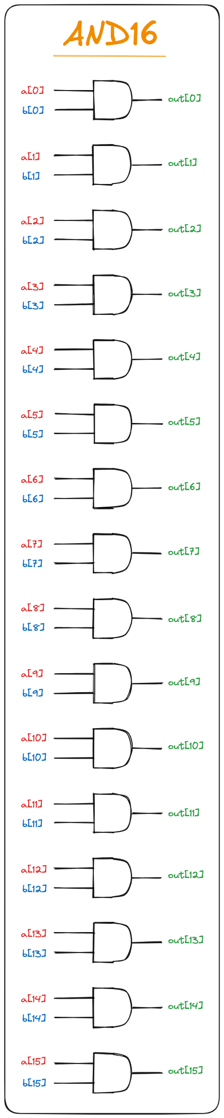
AND16
An n-bit And gate applies the Boolean operation And to every one of the n bit-pairs arrayed in its two n-bit input buses. This is how a 16-bit AND gate can be implemented which takes 2 16-bit inputs and produces a 16-bit output.
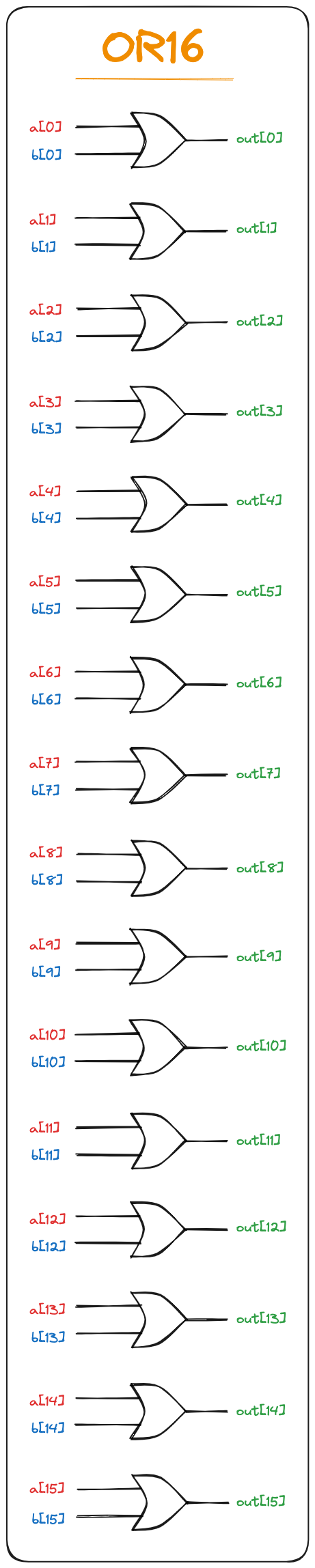
OR16
An n-bit Or gate applies the Boolean operation Or to every one of the n bit-pairs arrayed in its two n-bit input buses. This is how a 16-bit OR gate can be implemented which takes 2 16-bit inputs and produces a 16-bit output.
MUX16
An n-bit multiplexor is exactly the same as the binary multiplexor described before, except that the two inputs are each n-bit wide and the selector is still a single bit. A 16-bit MUX gate can be built in exactly the same way as the previous 16-bit gates (using 16 1-bit MUX gates).
Multi-Way versions of logic gates
Many 2-way logic gates that accept two inputs have natural generalization to multiway variants that accept an arbitrary number of inputs. Described below are some variants that will be needed later to build the final computer.
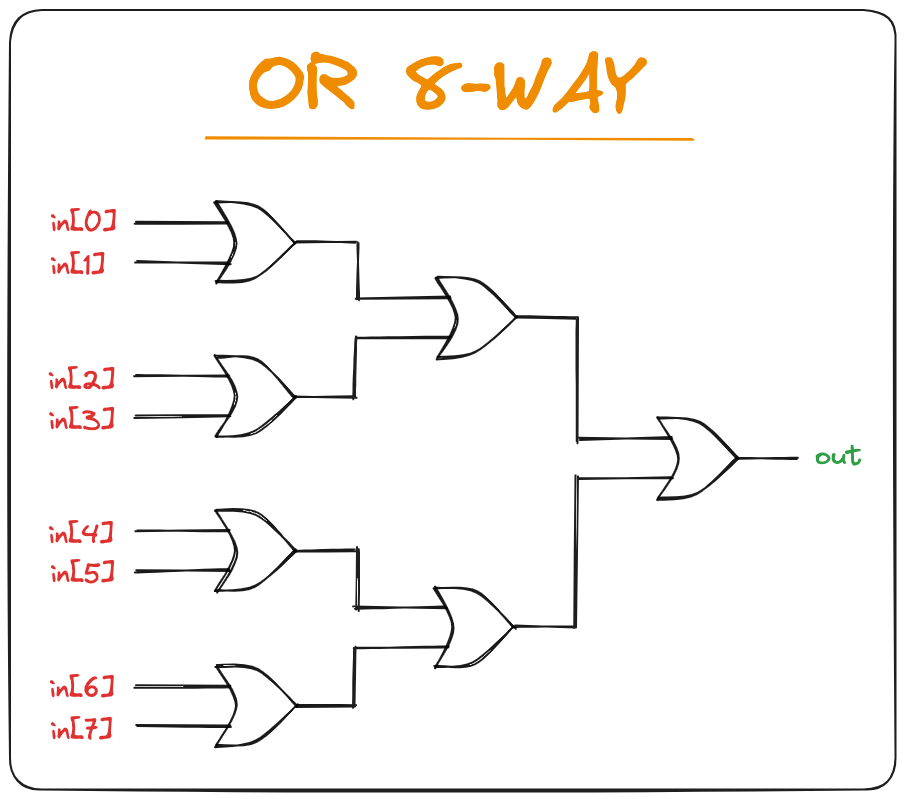
OR 8Way
An $n$-way OR gate outputs 1 when at least one of its $n$-bit inputs is 1, and 0 otherwise. We need an 8-Way OR gate which takes an 8-bit input and produce a 1-bit output which is the OR of all individual input bits. It can be implemented as:
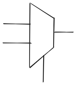
MUX 4Way16
An $m$-way $n$-bit multiplexor selects one of $m$ $n$-bit input buses and outputs it to a single $n$-bit output bus. The selection is specified by a set of $k$ control bits, where $k = \log_{2}{m}$. This gate takes 4 16-bit inputs and a 2-bit selection and produces 1-bit output (choosing 1 of 4 inputs based on selection bit).
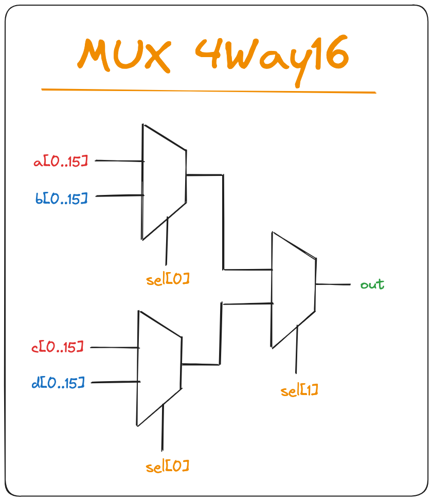
The truth table would be:
| sel[1] | sel[2] | Out |
|---|---|---|
| 0 | 0 | a |
| 0 | 1 | b |
| 1 | 0 | c |
| 1 | 1 | d |
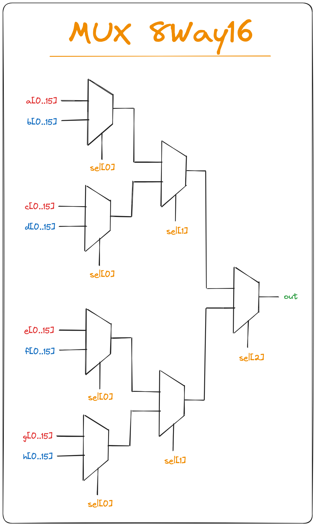
MUX 8Way16
This gate takes 8 16-bit inputs and a 3-bit selection and produces 1-bit output (choosing 1 of 8 inputs based on selection bit).
DMUX 4Way
An $m$-way $n$-bit demultiplexor channels a single $n$-bit input into one of $m$ possible $n$-bit outputs. The selection is specified by a set of $k$ control bits, where $k = \log_{2}{m}$. This gate takes 1 input and a 2-bit selection and produces 4 outputs (routing the input to 1 of 4 outputs based on selection bit).
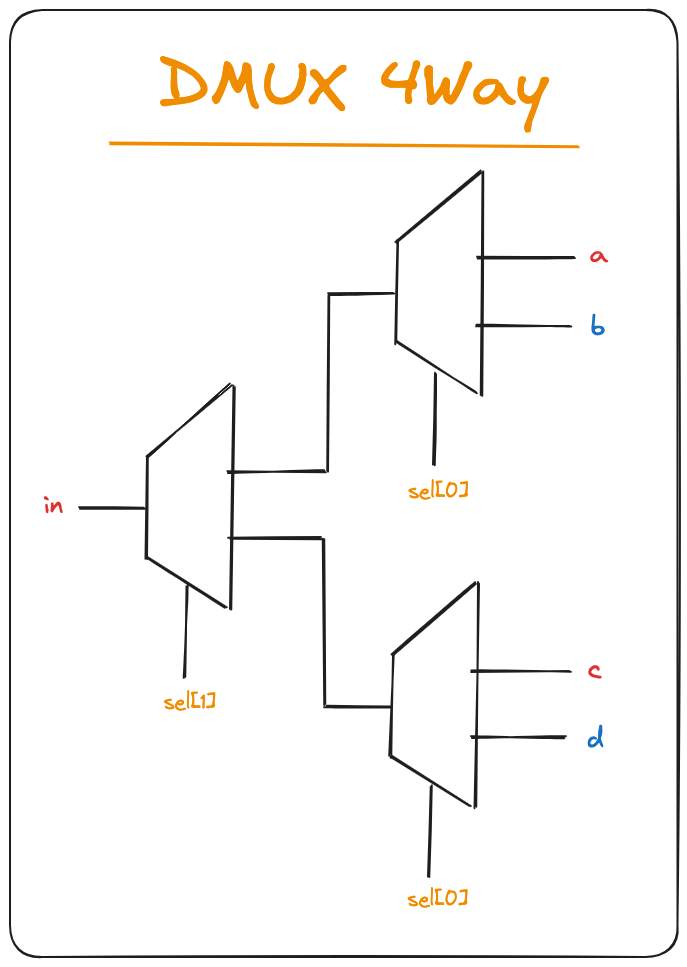
The truth table would be:
| sel[1] | sel[2] | a | b | c | d |
|---|---|---|---|---|---|
| 0 | 0 | in | 0 | 0 | 0 |
| 0 | 1 | 0 | in | 0 | 0 |
| 1 | 0 | 0 | 0 | in | 0 |
| 1 | 1 | 0 | 0 | 0 | in |
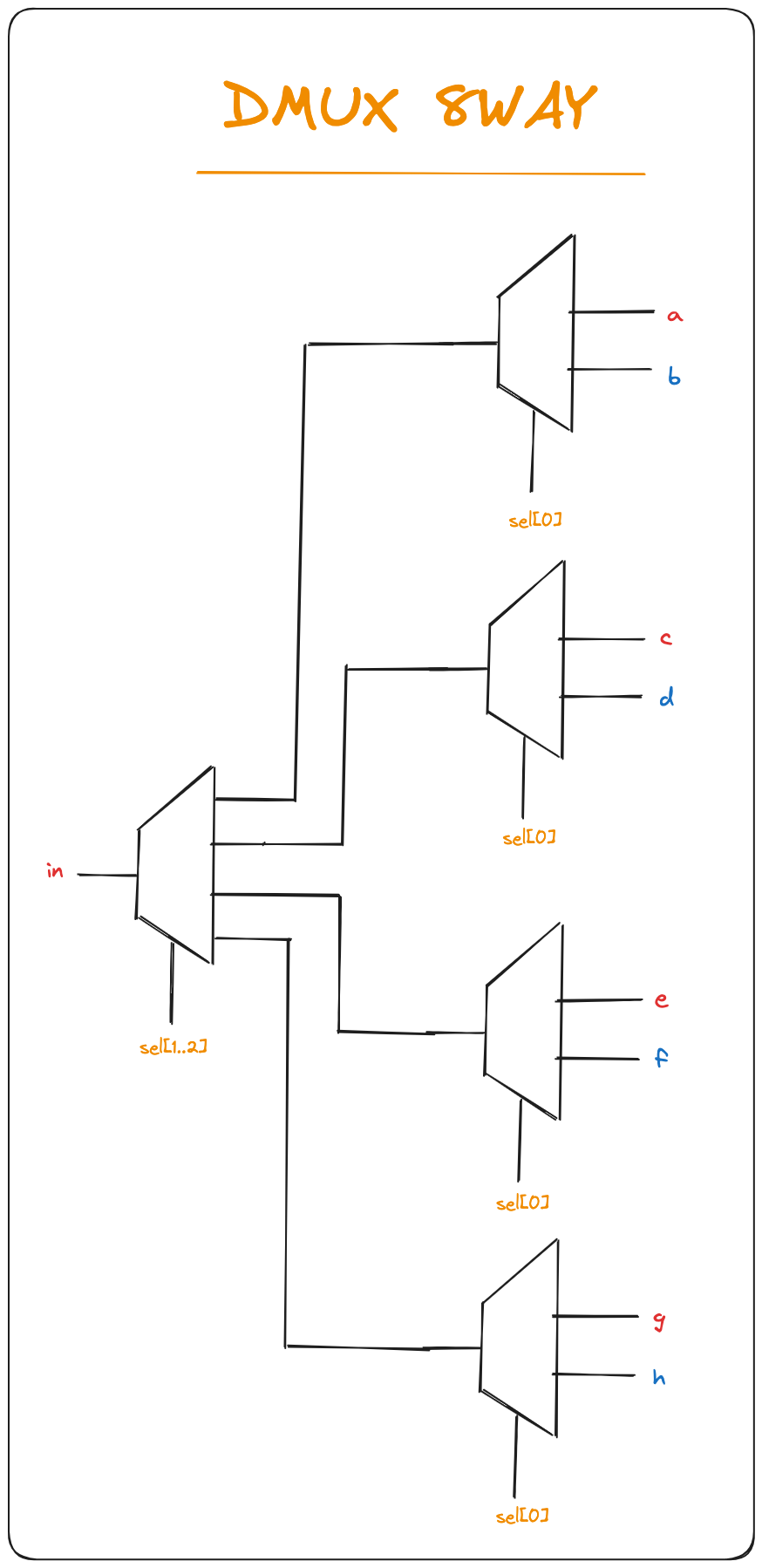
DMUX 8Way
This gate takes 1 input and a 3-bit selection and produces 8 outputs (routing the input to 1 of 8 outputs based on selection bit).
Adders
We can now mover on to adders which are designed to add two $n$-bit numbers.
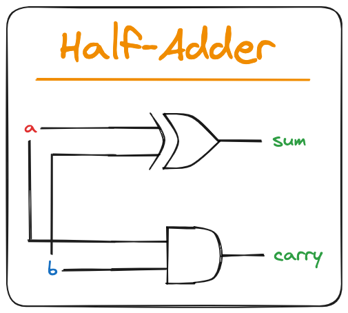
Half-Adder
A Half-Adder is designed to add two bits. It takes 2 inputs and produces 2 outputs (a sum bit and a carry bit). The truth table is:
| a | b | carry | sum |
|---|---|---|---|
| 0 | 0 | 0 | 0 |
| 0 | 1 | 0 | 1 |
| 1 | 0 | 0 | 1 |
| 1 | 1 | 1 | 0 |
It can be implemented using a XOR and an AND gate.
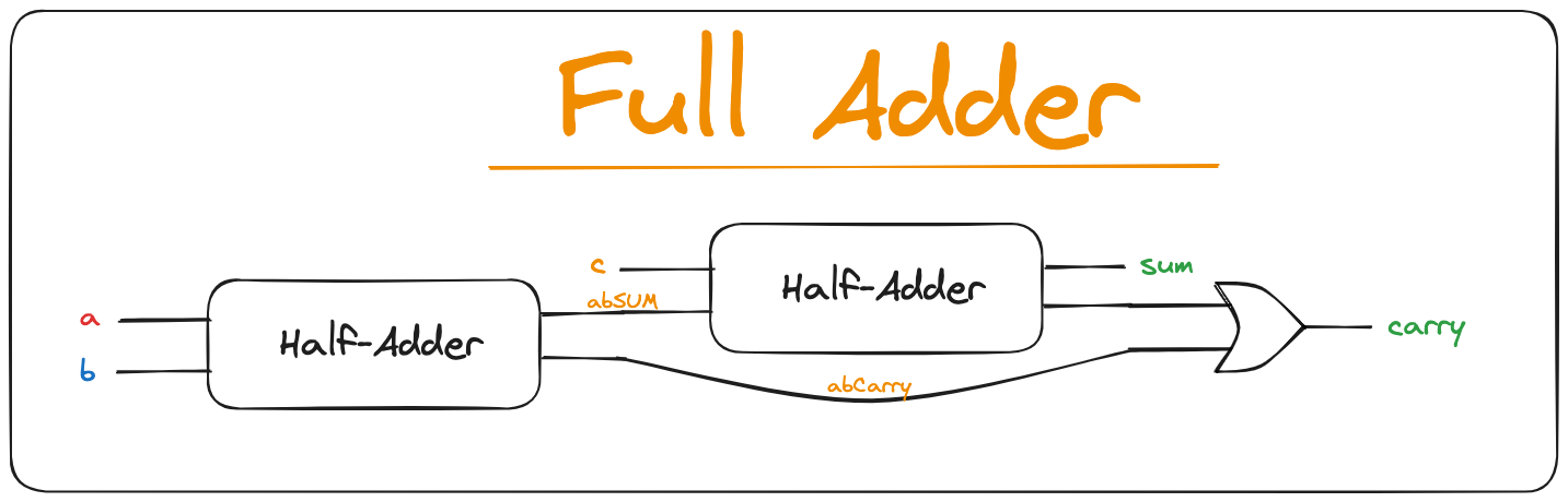
Full-Adder
A Full-Adder is designed to add three bits. It takes 3 inputs and produces 2 outputs (a sum bit and a carry bit). The truth table is:
| a | b | c | carry | sum |
|---|---|---|---|---|
| 0 | 0 | 0 | 0 | 0 |
| 0 | 0 | 1 | 0 | 1 |
| 0 | 1 | 0 | 0 | 1 |
| 0 | 1 | 1 | 1 | 0 |
| 1 | 0 | 0 | 0 | 1 |
| 1 | 0 | 1 | 1 | 0 |
| 1 | 1 | 0 | 1 | 0 |
| 1 | 1 | 1 | 1 | 1 |
It can be implemented using the previous Half-Adder and an OR gate.